Capabilities & Specifications
Every figure on this page is authoritative for the whole site. Where a specification appears elsewhere on ipcb.cc, the value published here governs. All data reflects current in-production process windows, not laboratory limits.

Specifications are process windows, not laboratory limits
A number a shop can only reach on a good day is not a capability. Every figure published here is what the line holds in routine production, which is why this page governs the rest of the site: where the same specification appears on a product page, the value here wins.
- Ranges are quoted against a defined stackup, copper weight and finish — send the drawing and we hold them
- Any parameter outside this window is reviewed by a process engineer before it is promised
- DFM review is part of every order, not a paid extra
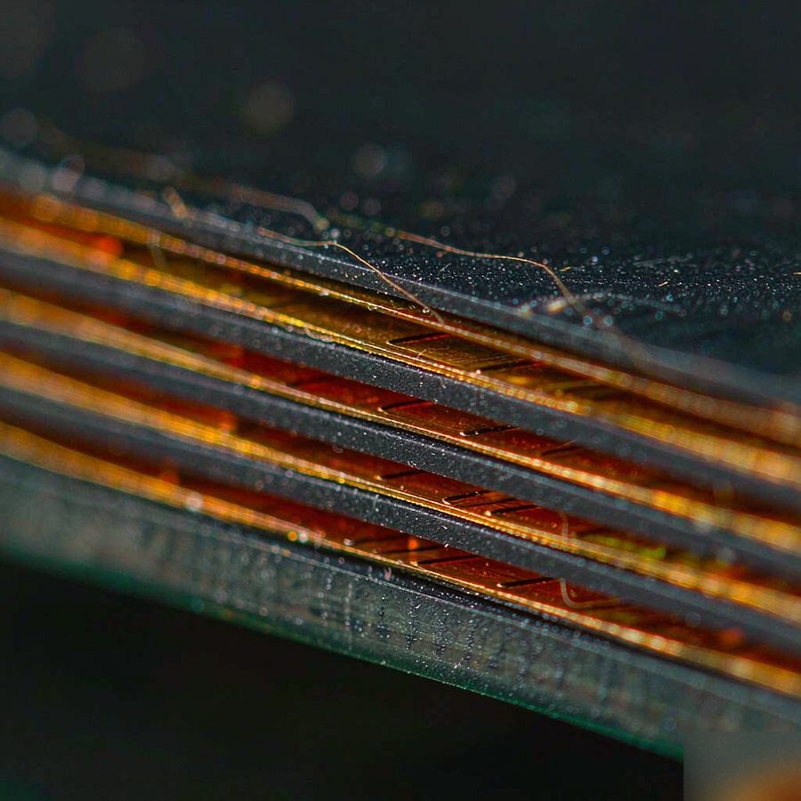
Fabrication specification
| Layer count | 1–44 layers (20+ on a dedicated high-layer line) |
| Rigid board types | Multilayer, HDI, thick copper, metal core, ceramic, backplane |
| Flex board types | Single-sided FPC, double-sided FPC, multilayer FPC, rigid-flex |
| Finished copper weight | 1–13 oz (outer base copper up to 18 oz); standard 3.5–10 oz |
| Board thickness | 0.25–8.0 mm (standard 0.4–3.5 mm) |
| Maximum panel size | 610 × 1100 mm |
| Minimum trace / space | 2/2 mil — 0.05 mm |
| Trace width accuracy | ±8 µm |
| Controlled impedance tolerance | ±8% |
| Aspect ratio | 8:1 standard, up to 20:1, backplanes up to 25:1 |
| HDI | 1–3 stage laser blind vias; minimum laser via 0.10 mm |
| Minimum mechanical drill | 0.15 mm (0.20 mm standard) |
| Copper-to-edge clearance | 0.30 mm minimum |
| Solder mask | LPI, matte / gloss, black / green / blue / red / white |
| Silkscreen | White, black or yellow, 0.15 mm minimum line |
| Impedance control | Single-ended and differential, tested with coupons |
Substrate materials
Grades we stock and run routinely. If your design calls for a material not listed here, send the datasheet — we will confirm availability and process window before quoting rather than after.
| Standard FR-4 | Tg 130–140°C, general-purpose multilayer |
| High-Tg FR-4 | Tg 170–180°C, lead-free assembly and thermal cycling |
| Halogen-free | IEC 61249-2-21 compliant, for regulated markets |
| High-frequency | Rogers, Taconic, Panasonic M6/M7, TUC |
| Polyimide | Flexible and rigid-flex substrates, high temperature stability |
| Aluminium core | Thermal conductivity 2–12 W/m·K |
| Copper core | Thermal conductivity 2–12 W/m·K, higher current capacity |
| Ceramic | Al₂O₃ / AlN, thermal conductivity up to 170 W/m·K |
Surface finishes
| ENIG | Immersion gold over nickel — flat, good for fine pitch and BGA |
| Lead-free HASL | RoHS compliant, cost-effective for through-hole |
| OSP | Organic solderability preservative, flat, short shelf life |
| Immersion silver | High-frequency friendly, good solderability |
| Immersion tin | Flat, good for press-fit |
| Hard gold | Gold over nickel on edge connectors and keypads |
| ENEPIG | Electroless nickel electroless palladium immersion gold, wire-bondable |
Assembly & value-added
| Assembly types | SMT, through-hole (DIP), mixed technology, BGA / QFN / CSP |
| SMT capacity | Four lines, 500,000 placement points per day |
| Placement accuracy | ±0.03 mm (chip), ±0.05 mm (QFP) |
| Smallest component | 01005 (0.4 × 0.2 mm) |
| Component sourcing | 70,000+ SKU library, 35+ procurement specialists, authorised distributors only |
| Inspection | AOI, X-ray (BGA voiding), SPI, ICT / flying probe, FCT |
| Conformal coating | Acrylic, silicone and polyurethane, selective or full-board |
| Box build | Enclosure assembly, cable assembly, labelling, drop-ship packaging |
FPC & rigid-flex
Flexible circuits are built to the same inspection standard as rigid boards, with additional checks for bend radius and stiffener bonding.
| FPC types | Single-sided, double-sided, multilayer; air-gap and multilayered with coverlay |
| Base material | Polyimide (PI), adhesive-based and adhesiveless constructions |
| Coverlay | PI coverlay or photo-imageable coverlay (PIC) |
| Stiffeners | FR-4, polyimide, stainless steel, aluminium; PSA or thermal-bonded |
| Minimum line / space | 3/3 mil (0.075 mm) on standard polyimide |
| Bend radius | Typically 10× total thickness for dynamic flex, 5× for static flex |
| Surface finish | ENIG, immersion silver, immersion tin, OSP |
| Rigid-flex | 2–20 layers rigid section, controlled impedance across the flex transition |
Lead time by build class
| Build class | Fastest achievable |
|---|---|
| 2-layer prototype | 24 hours |
| 4–6 layer | 48–72 hours |
| 8+ layer | 5–7 days |
| High-layer count & HDI | 7–15 days |
| Flex & rigid-flex | 5–10 days |
| Assembly (turnkey) | Add 3–7 days after components arrive |
Fastest achievable means the quickest we have shipped that class of build, not a standard commitment. Actual lead time depends on layer count, material availability, drill aspect ratio and whether impedance coupons are required. Ask for a committed date with your quote.